Arduino LED Project
Projects items :
- Arduino Uno
- Breadboard
- 2 x Jumper Wires Male to Male
- 1 x LEDs
- 1 x 220 Ohms Resistor
In this tutorial, we will learn how to use your Arduino Uno to control LEDs. This is a pretty simple project and will help us learn how to use sensors and modules as these are programmed in the same way.
The Arduino communicates with modules and sensors by switching on and off electrical current. It’s very similar to the one’s and zero’s in binary code. When current is switched on, it’s known as a “HIGH signal”. That’s comparable to the “one” in binary code. When the current is switched off, that’s a “LOW signal”, which is similar to the zero in binary code. The length of time the current stays on or off can be changed from a microsecond up to many minutes.
A resistor is a component that resists the flow of electrical energy. It converts some of the electrical energy into heat. If you put a resistor in series with a component like an LED, the resistor will use up some of the electrical energy and the LED will receive less energy as a result. This allows you to supply components with the amount of energy they need. You use a resistor in series with the LED to keep it from receiving too much voltage. Without the resistor, the LED would be brighter for a few moments, but quickly burn out
LEDs need to have a resistor placed in series (in-line) with it. Otherwise, the unrestricted current will quickly burn out the LED. The resistor can be any value between 100 Ohms and about 10K Ohms. Lower value resistors will allow more current to flow, which makes the LED brighter. Higher value resistors will restrict the current flow, which makes the LED dimmer.
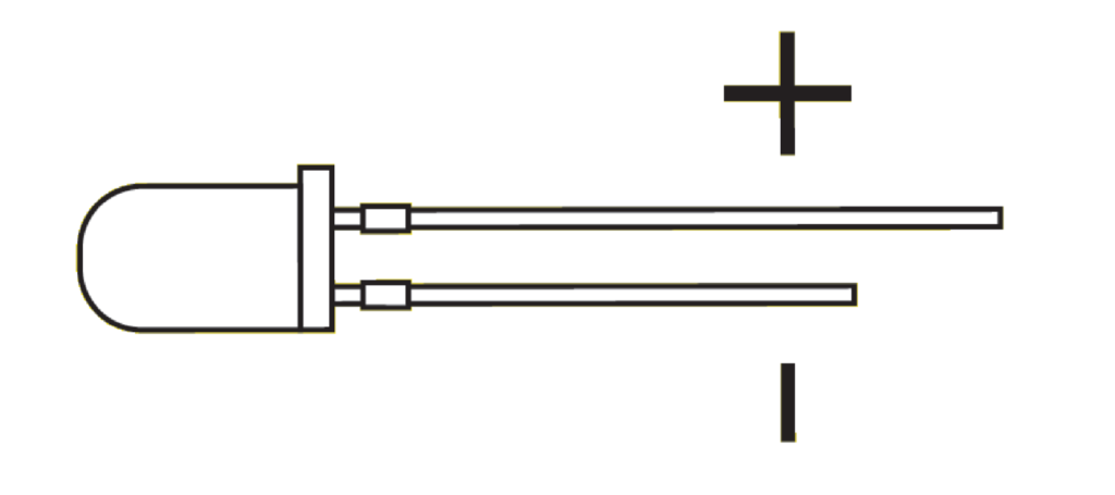
Also, most LED’s have polarity, which means that they need to be connected the right way around. Usually, the LED’s shortest lead connects to the ground side.
LEDs need to have a resistor placed in series (in-line) with it. Otherwise, the unrestricted current will quickly burn out the LED. The resistor can be any value between 100 Ohms and about 10K Ohms. Lower value resistors will allow more current to flow, which makes the LED brighter. Higher value resistors will restrict the current flow, which makes the LED dimmer.
Also, most LED’s have polarity, which means that they need to be connected the right way around. Usually, the LED’s shortest lead connects to the ground side. Figure 2
If you connect the LED to pin 2 as shown in the image below, you can use the same code we used above to make the LED flash on and off.

/**Alphatronic Starter Kit V1
2022 Feb
This Tutorials is created to help you learn the basics of arduino
visit alphatronic.lk for more information
**/
void setup() {
  pinMode(2, OUTPUT);
}
void loop() {
  digitalWrite(2, HIGH);
  delay(1000);
  digitalWrite(2, LOW);
  delay(1000);
}